
BudgetBoi
A 12lb battlebot built on a budget.
Ryan Duarte, MIT
Description
An open-source 12-pound 3D-printed battlebot that’s also budget friendly.
Introduction
Combat robotics, frequently referred to as Battlebots, is a hobby where builders make durable machines meant to completely dismember or control their opponents. Competitors vary from all walks of life, including engineers, teachers, chefs, plumbers, students, and far more. By building robots, many learn how to use CAD and manufacturing technology like additive manufacturing, CNC machining, and laser cutting.
In combat robotics, the 12-pound “hobbyweight” weight class is the first chance many builders get to create larger robots. However, this also makes the weight class expensive and inaccessible. Many competitors take advantage of access to waterjets and CNC machines for reduced or no cost. For those without these resources, outsourcing custom parts or buying a kit is often too expensive. For example, a newly released 12-pound kit which only pushes opponents around the arena costs $1200.

Problem Statement
The 12-pound weight class in combat robotics is expensive for those without access to complex machinery. Aspiring builders on tighter budgets such as high school students are effectively barred from competing at a larger scale.
Project Goal
To develop an open-source 12-pound battlebot that is low-cost and requires minimal manufacturing process. It should also allow the user to customize it to their own preferences.
Team Members
Ryan Duarte - Project Originator and Concept Designer
Ron Durham - Liaison, 3D Printing Specialist, and Project Coordinator
Specifications
Weight: 9.6 lbs.
Filaments used: PLA+, TPU
Dimensions of largest printed part: 220mm x 189.35mm x 63.4mm
Cost:
Lifter version: ~$631 before taxes and shipping
No lifter (just a wedge): ~$494 before taxes and shipping
Tools needed:
Allen keys (1.3mm, 1.5mm, 2mm, 2.5mm, 3mm, 5mm, 5/64inch, 7/64 inch, 3/16in)
10mm wrench
Soldering iron, solder, wire strippers
ESC programmer
Needle nose pliers, snap ring pliers
Blue Loctite
Drill with 1/8” drill bit
Vise or an arbor press.
File
Rat tail file
STL, CAD, and Firmware Files
Find the direct link to the Onshape CAD here: BudgetBoi CAD Files
Also find the .hex and ESC settings here: XXXXXXXXXXXXXXXXXX
BOM
The BOM can be found at the following link: BudgetBoi BOM
Slicer Settings
Assembly Steps
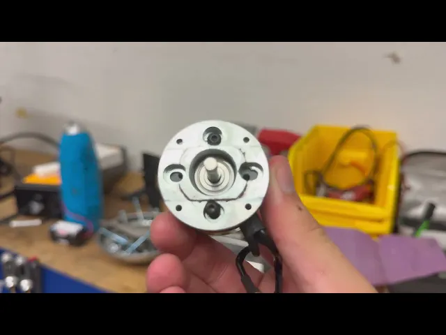
Drivetrain
Remove the shaft collar, shims, and snap ring from the shaft of the Tempest 2221 (small Tempest motor).
Reapply the shims and shaft collar, but do not tighten the set screw. Simply let it slide along the shaft.
Loosen the set screw located in the can where the shaft passes through.
Press the gearbox pinion onto the shaft so they are flush.
Attach the gearbox motor plate to the motor using m3x6 buttonheads.
Press the shaft back through the motor until the pinion sticks out 0.5mm from the upper face of the motor plate.
Remove the motor plate.
Apply Loctite to the shaft collar and the set screw in the can, tighten both.
Reattach motor plate with Loctite and m3x6 buttonheads.
Attach motor plate to gearbox with Loctite, thereby completing the gearmotor.
Slide the TPU squish zone over the gearbox, attach via 4 m4x8 buttonheads Loctite.
Attach PLA+ motor cover to TPU squish zone with m4x16 buttonheads, m4 nuts, and Loctite.
Slide 17mm bearing (small open bearing) into bore in the back of the motor cover.
Screw small PLA+ bearing retainer into the back of the motor using 3 m2x10 screws, use Loctite. When done, the bearing should be held securely in place.
Repeat steps a-n for second drive motor.
Push motors into their pockets in the side walls. It is a tight fit and does need a lot of force. Attaching a wheel (described by steps r-s below) to the shaft is helpful, wiggle shaft side-to-side.
Bolt TPU squish zones to frame using 4 m4x16 buttonheads and m4 nuts, use Loctite.
Slide wheel hub down shaft, leave a 3mm gap to frame. Tighten both set screws with Loctite. Ensure the longer set screw rests flat along a flat on the hex shaft.
Put the wheel over the hub and use snap ring pliers to attach the snap ring to hold the wheel on.
Repeat p-s for other motor/wheel.
Armor
Wedge
Lay the wedge flat on the ground. The rectangular cutouts are on the bottom half of the wedge. The cutouts are skewed towards the right side of the wedge. When oriented in such a manner, the front faces upwards.
Slide the backs of the forks through their slots in the front of the wedge. They should be angled downwards.
Slide the ¼” socket head screws through the right side of the bores in the backs of the forks. Secure a ¼” nut on the other side. Use Loctite. This prevents the forks from sliding out through the front of the wedge.
TPU nutstrips
With a soldering iron, mount the m6 heat inserts into the TPU nutstrips. Ensure they go in straight. The m6 screws go through the entire nutstrip before interfacing with the heat inserts, therefore a slight misalignment could be impactful. The heat inserts go on the sides with larger bores.
Assembly
Position the nutstrips on the inside fronts of the side walls. The flange should cover the angled part of the frame’s side walls.
Position the wheel guards along the outside of the side walls.
Run the m6 socket heads through the wheel guards, through the frame, and through the nutstrips into the heat inserts at the ends. Use Loctite. Ensure the front faces of the wheel guards and side walls are flush.
Insert lifter bearing into lifter bearing bracket. Insert assembly into the pocket in the outer right frame wall. Use 2 m4x16 buttonheads and nuts with Loctite to bolt in place.

Electrical system
Wiring
See attached wiring diagram.
Ensure positive lead from battery to switch is soldered to the terminal closest to the screw head. The bottom terminal is constantly in contact with the screw, meaning if the battery connector is soldered to it, the screw will always be live.
The capacitors have a side with negative symbols. Solder this leg to the negative terminals of the ESC power input.
ESC firmware
Configure Repeat 35A ESCs to match the included screenshot. Once done, change motor kv to 900kv.
Flash the Sequre with included firmware. Then configure to match included screenshot. Once done, change motor kv to 740kv.
Lifter
Reference the video below for lifter instructions:
Final Assembly
Use m2x12 buttonheads and nuts with Loctite to mount switch to the back of the frame. Reference CAD if needed.
Use m4x20 buttonheads and nuts with Loctite to mount TPU lifter mounts to frame.
Insert lifter bearing retainer into place, use 3 m3x10 buttonheads with Loctite to bolt in place.
Bolt 6-32 nutstrips into place along the top of the frame side walls.
Use 6 m6x22 hex heads to bolt wedge onto front. Loctite recommended.
Use 6 6-32 buttonheads to bolt top plate into place.
Celebrate :)


